Fluid
If
somebody proposes a method to propel a spacecraft from the inside (without
expelling mass) by manipulating a 100k mass so it bumps against the
spacecraft’s inner hull, I can knowingly state it is not possible, not by automatically citing a
physical law or principle (that
would be lazy), but because we can represent all the interaction with a few
calculations and the results will be 0.
Example:

Fig a
Fig 1 illustrates
2 masses in a microgravity environment, mass 1 (M1) is a pressurized structure
(spaceship), inside the spacecraft there is a 100k mass (M2) positioned at the
forward (+X) inner hull.
For simplicity we shall
assume that M1 and M2 both have a mass of 100k.
There is a piston cylinder (fig a) that can exert a strong force
pushing M2 in the –X direction when activated.

Fig b
When the piston
cylinder is activated, it gives mass (M2) a push with a force (F2) of 100n,
mass M2 will accelerate (a2) 1m/s in the “rear” –X direction (fig b).
As for every
force there is an equal and opposite reaction, the pressurized structure (M1)
will receive a 100n force (F1) in the +X direction gaining a V1m/s. (1)
acceleration (fig b).

Fig c
As mass M2
travels towards the opposite hull (-X) with a constant velocity (V2) of 1m/s, no forces are exerted on mass (M1) therefore it
travels in a continuous velocity (V1)

Fig d
When M2 collides
with mass M1’s “rear” (-X) hull, as the velocity (V2) is unchanged, (1m/s) the force (F4) will be 100n =1m/s * 100k
As mass M1
received a 100n force in the +X direction (fig 2) and a 100n force in the –X
direction (fig 4) the net change in velocity is 0.
The above
description(figs a to d) is valid in a vacuum, yet as M1 is a pressurized
structure, mass M1’s velocity will decrease
slightly affected by the force of air drag, we can increment said force
(air drag) by using an air brake such as a parachute or a shape with a high
drag coefficient.
Effect of drag on M2’s velocity

Fig e
The instant M2
receives a 100n push, it accelerates to 1m/s in the –X direction, if the
following instant an air brake (in this example a parasite) is deployed, M2’s
–X velocity will decreases from an initial velocity (Vi) of 1m/s to a final
velocity (Vf ) just before the collision.
In this example
we shall assume Vf =0.9 m/s, in the next segment we shall try to calculate the
forces of drag on mass M2 using the drag equation.

Fig f
When mass M2
collides with the spacecraft’s inner hull with a velocity of 0.9m/s it exerts a
force of 90n (90n = 0.9m/s * 100k) on the spacecraft.
As the spacecraft
received a 100n “push” in the +X direction (fig 2) and a 90n force in the –X
direction it will gain a 0.1 m/s acceleration in the +X direction.
The Fluid Space
Drive V3 (FSD) is a method of propulsion in microgravity environments that has
no need to expel propellant to generate thrust.
It does this by
propelling a mass (M2) inside the FSD from one end of the spacecraft to the opposite end but modifying the mass’s
drag coefficient decreasing it’s velocity when traveling to the rear end of the
spacecraft (M1)
What follows
below is a step by step description of the method and the corresponding
calculations (you can see a simple “tongue in cheek” description of the method here).
First the FSD’s dimensions (for this simulation):

![]()
Fig 1
Fig 1 shows a pressurized structure (M1) or spacecraft in a micro-gravity environment, inside the spacecraft is a 100k mass (M2) we call Ram Mass Assembly or RMA.
The RMA has freedom to move across the length (not breadth) of the spacecraft.
The pressurized
structure (mass M1) is 30m long with a radius of 1,5 meters, the skin is 6mm
aluminum (more or less Lunar Lander) (1),
M1’s mass will be 808,02 k (2)


Fig 2
Fig 2 illustrates
the RMA (M2), it has a series of flaps attached to servo motors, when the flaps
are closed they form the shape of an open cylinder that functions as an air
brake increasing the RMS’s drag coefficient (note Dd)
therefore slowing it’s relative velocity inside the pressurized structure (M1).
Note: The
illustration does not show the ideal aerodynamically shape for low drag, see note 3 for a better design
|
Recap |
|
M1 (pressured structure) mass = 808.02 k |
|
M2 (RMS) mass = 100 k. |
Cycle 1 (forward ramming piston is activated)

![]()
Fig 3
The forward ramming piston is
activated with a 400n force giving the RMA (M2) a push (F1) in the –X direction (Fig x) accelerating it in the –X direction
(a2) with to 4 m/s (formula 1)

Formula 1
The opposite
force (F2) gives the pressurized structure an
acceleration in the +X direction (a1) of 0,495 m/s
(formula 2).

Formula 2
![]()
Fig 4
As mass M1 is traveling unhindered (4) in the +X at 0.495 m/s (V1) it’s
velocity will remain constant until another force is applied.
Mass M2 is traveling in a pressurized
environment, the fluid (air) exerts a force (drag) as it encounters the air
brake decreasing M2’s –X velocity.
The drag force can be calculated by using
the drag equation (formula 1).
Fd = 0.5 * p * v² * A * Cd
Fd= drag force.
P= mass density of fluid (At 20 °C and 101.325 kPa, dry air has a density of 1.2041 kg/m3) in this example we will use 1.2 kg/m3 (x)
V= Velocity in m/s
A = surface of the 1m radius air brake (3.1415 m2)
Cd = drag coefficient for an open cone 2.2 (note Cd)
Formula 3
Therefore using the above data we get:
![]()
Formula 4
The 66.350n force pushing in the +X
direction will change M2’s velocity by 0.6635 (formula 5) resulting in a final
velocity (for this time interval) of 3.3364 m/s (formula 6)

Formula 5

Formula 6
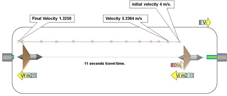
This calculation
is to be repeated every time interval until M2 collides with M1’s inner rear
hull with a final velocity of 1.4071398
|
Column A = time interval (1 second) Column B = total displacement of mass M1 at time interval. Column C = total displacement of mass M2 at time interval. Column D = Velocity of mass M1 at time interval. Column E = Velocity of mass M2 at time interval. Column F = Drag on M2 at time interval.
Drag change (M2)
Velocity change (M2) |

Fig 5
|
For M1 (spaceship) |
|
|
Elapsed time |
11 s |
|
Distance travelled |
5.44 m |
Fig 6
Recap
After the 400n force is exerted, the elements do the
following:
M1 travels in the +X direction at 0.495 m/s constant
velocity (formula 2).
M2 travels with an initial velocity of 4 m/s but is
slowed by the drag generated by the air brake, it travels for 11 seconds until
it collides with M1’s inner rear hull with a final velocity of 1.325 (Fig 5)
End of cycle 1
Cycle
2: M2 collides with M1’s rear (-X) inner hull.

![]()
Fig 7
The instant M2 contacts M1 an
electromagnet (not shown) is activated to prevent any “bounce” insuring the
collision is inelastic.
Therefore we have two masses (M1 and M2)
that have an inelastic collision, to find the final velocity we use the
formula:

Formula
7
Where M1 = mass
of body 1
M2 = mass of body
2
V1 = Initial velocity of body 1
V2 = Initial velocity of body 2
v = Final velocity of both the bodies
The final velocity for inelastic collision
is given by:

Formula 8

Formula 9
Therefore M1 and M2 are traveling in the
+X direction at 0.294591 m/s after inelastic collision 1
For simplicity we permit masses M1 and M2
to travel together at 0.294591 m/s for 1 time interval (1 second), traveling at
this time a distance of 5.7399 meters in 12 seconds the +X direction.
End of cycle 3
|
For M1 (spaceship) |
|
|
Total elapsed time |
12 s |
|
Distance travelled |
5.7399 m |
Cycle
4: The rear ramming piston is activated with a 200n force.

![]()
Fig 8
The rear ramming piston is
activated with a 200n force, this gives the RMS (M2) a push (F5) in the +X direction (Fig 8) accelerating it in the +X direction
(a2) with to 2 m/s (formula 10)

Formula 10
As M2 was traveling with an initial
velocity of 0.2945 m/s when the acceleration is added it has a final velocity
of 2.2945 m/s
The opposite
force (F6) gives the pressurized structure (M1) an
acceleration (velocity change) of 0.24752 m/s in the -X direction (formula 11).

Formula 11
As M1 had an
previous velocity of 0.294591 m/s (formula 9) it’s present velocity (formula
12) is 0.047075 (V1 + V2 = 0.294591 - 0.24752 = 0.047071)

Formula 12
As M2 travels
inside M1 (fig 9) its velocity is decreased by drag, but because the air brake
is deactivated (flaps in open position) its drag coefficient is only 0.3, M2
“catches up” to M1’s inner hull in time interval 29 (29 seconds from start of
cycle) with a velocity of 1,6 m/s (M2 velocity of 1.7 – M1 velocity of 0.004)
|
Column A = time interval (1 second) Column B = total displacement of mass M1 at time interval. Column C = total displacement of mass M2 at time interval. Column D = Velocity of mass M1 at time interval. Column E = Velocity of mass M2 at time interval. Column F = Drag on M2 at time interval.
Drag change (M2)
Velocity change (M2) |
Fig 9

![]()
Fig 10
After 17 second
of travel (29s from start of cycle fig 3) in the +X mass M2 “caches up” with
mass M1 colliding with M1’s forward inner hull (Fig 11)

![]()
Fig 11
The instant M2 contacts M1 an
electromagnet (not shown) is activated to prevent any “bounce” insuring the
collision is inelastic.
Therefore we have two masses (M1 and M2)
that have an inelastic collision, to find the final velocity we use formulas 13
and 14:
Formula
13
Where M1 = mass
of body 1
M2 = mass of body
2
V1 = Initial velocity of body 1
V2 = Initial velocity of body 2
v = Final velocity of both the bodies
The final velocity for inelastic collision is given by:
Formula 14

Formula 15
For simplicity we permit M1 and M2 to travel
together for one time interval (1s), it will advance an additional 0.229931m
With this action
in time interval 30 (seconds) M2 is in its original position (attached to M1’s
forward inner hull) and the propulsion cycle is complete, therefore we have
that M1 (the spaceship) has traveled a total of 6.75m in 30s.
|
Parameters at end of cycle For M1 (spaceship) |
|
|
Total elapsed time |
30 s |
|
Distance travelled |
6.77 m |
With the above
parameters we can calculate how much M1 (the spaceship) has accelerated using
formula 16

Formula 16
The spacecraft
has an acceleration of 0.015044m/s.
At first glance
that does not seem like much, but as the spacecraft will be able to accelerate
continuously as long as electrical power is applied it will soon become the
fastest machine humanity has ever constructed.
Therefore, if we
start with 0 velocity:
In one minute it
will accelerate to 0.9 m/s
In one hour it
will accelerate to 54 m/s
In one day it
will accelerate to 1,296 m/s
In a week it will
accelerate to 9,072 m/s (in two weeks it will surpass Voyager II’s present
velocity of 15,400 m/s)
In one month it
will accelerate to 38,880 m/s
In one year it
will accelerate to 473,040 m/s
In one decade it
will accelerate to 4,730,400 m/s
Notes (NOT
COMPLETED YET)
Note 1: For this simulation an aluminum skin of
0.6 mm is used, for comparison the lunar lander’s walls were 0.012 inches thick
(0.3 mm).
It has been
pointed out to me that there are better present day materials with improved
strength to weight ratio, but we can use aluminum in this document as its
properties are well known.
Note 2: Calculating M1’s mass
M1 length (h) =
30 m
M1 radius = 1.5 m
Thickness of
aluminum skin = 0.6 mm = 0.0006 m
To calculate the
mass of the aluminum “skin” we calculate the volume of a cylinder 30 m by 1.5 m
and subtract the volume of a cylinder of the same dimensions – the thickness of
the skin.
Volume of cylinder
a = pi * r * r * h = 3.141592654 * 1.5 * 1.5 * 30 = 212.057504145
Volume of
cylinder b = pi * (r – 0.3 mm) * (r – 0.3 mm) * h = 3.141592654 * (2 - 0.0006)
* (2 – 0.0006) * (30 – 0.0012) = 211.8794166
Volume of skin =
Volume of cylinder a - Volume of cylinder b = 212.057504145 - 211.8794166 = 0.178087590 m3
We shall
increment the skin’s volume to 0.459784403 m3 (taking into account the
decimals) just to be on the safe side.
Mass of the skin = 0.178087590 m3 by mass of 1m3 of aluminum (2700k) =
480.83649 k.
To calculate the
mass of the air in the aluminum cylinder we multiply the volume of the inner
cylinder 211.8794166 by the mass of 1m3 of air 1.26 k.
Mass of air in cylinder = 211.8794166 by 1.26 = 226.968064916
k.
Total mass of FSD = Mass of the skin + Mass of air in
cylinder = 480.83649 + 226.968064916 = 707 k.
NOTE: we will
increment the total mass to 808k just to be on the safe side.
|
So
the mass we will use in this document for mass M1 is 808.02 k |
Note 3 RMS improved design.

Before we chant “Alpha Centauri here we come” conceder what percentage of the force excreted by the air drag on M2 is transmitted to the spaceship’s hull (nullifying the effect)
Let us include a factor pt (momentum transmitted) if pt=1 we will understand that all the force slowing M2 is transmitted to the spaceship’s hull, and if pt=0 no force is transmitted to the spacecraft.
The true pt value has to be determined by experimentation (just as the drag coefficient of various shapes is deduced by experiments), if pt has any value that is less than 1, then the method described in this document works as a practical method of propulsion in microgravity.
Assessment 1, decreasing M2 velocity by direct contact with the spacecraft (fig 7)
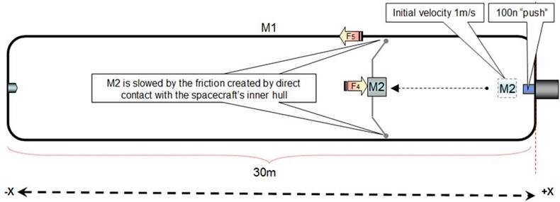
Fig 7
If M2 is slowed by the friction created by direct contact with the spacecraft’s inner hull (fig 7), all the force (F4) that is slowing M2 will be transmitted (F5) to the spacecraft (M1) and regardless of M2’s final velocity we can assume the spaceship (M1) will not gain any acceleration (therefore the pt factor is 1)
Assessment 2, decreasing M2’s velocity by air brake when diameter of spaceship is almost identical to air brake’s diameter (tight fit) (fig 8).
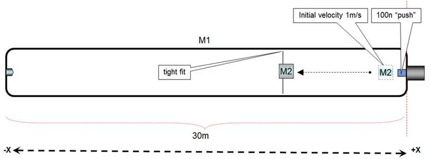
Fig 8
If the air brake’s diameter is a tight fit with the spacecraft’s diameter, it will act like a piston in a cylinder compressing the air in the –X side and come to a full stop before reaching the –X inner hull, and it is a logical assumption that the spacecraft will not gain acceleration in any direction.
Assessment 3, decreasing M2’s velocity by air brake when diameter of spaceship larger than the air brake’s diameter by a factor of X2 or more (fig 8).

Fig 8
If we increase the spacecraft’s diameter with relation to the air brakes, there will be sufficient space for the air to flow around M2 without greatly affecting the spaceships velocity, we can assume that the pt factor is less than one, and if we continue increasing the spaceship’s diameter (fig 9) the pt factor will decrease.

Experimentation on a test bed that contains an airtight box 50cm X 50cm by 3 meters have demonstrated that a “air brake” composed of a rigid flat 40cm by 40cm surface is successful in slowing the inner mass’s ( costume made dry ice pluck) velocity without affecting the box’s initial velocity (1)
This
has only been tried at relative low velocities (not more than 1.4 m/s). It has
been pointed out that by modifying the parameters described in this document,
specifically increasing the force exerted by the forward ramming piston on M2 so that its initial velocity is
incremented will greatly increase the acceleration created at the end of the
propulsion cycle, that may be true on paper but I have no idea (as yet) at what
velocity (supersonic?) the air may behave in a different manner so as to become
counterproductive.
Although test with different masses and
higher velocities are being programed, at the present time high velocity (near
supersonic) test are not in the works.
|
The drag coefficient of a shape is determined
through experiments, and it depends on parameters, such as the body shape, Reynolds
number and surface roughness. The values of the drag coefficient for
basic body shapes in gas are available from various sources in literature and
online. Drag coefficient of shapes used in this
document have been obtained by information made available by Nasa, and other
sources. https://www.grc.nasa.gov/www/k-12/airplane/shaped.html http://www.aerospaceweb.org/question/aerodynamics/q0231.shtml The table at right is work of Mohammad Sadraey, Associate
Professor at Daniel Webster College’s Department of Engineering and Computer
Sciences. |
http://faculty.dwc.edu/sadraey/Chapter%203.%20Drag%20Force%20and%20its%20Coefficient.pdf |

This document is a work in progress
William John Elliott S.
February 2014