Contact Information
William John Elliott S.
56-2-2042863
56-9-85520114
william.john.elliott
(contact on Skype)
http://www.wjetech.cl/
wjeconsultant@gmail.com
wje@wjetech.cl
Simple description of proposal (
Introduction
This
document is intended to explain how (and why) a
I understand that
you are tempted to reject the proposal “out of hand” because you KNOW it is
impossible to accelerate a closed system without expelling mass (very basic
physics).
And yet I present
a simple method of propulsion that permits spacecraft in a micro-gravity
environment to accelerate for extended periods of time in order to obtain a
very high velocity without expelling mass. (What has been called a propellantless space drive.) Please read to the end before judging.
Basic
elements of a
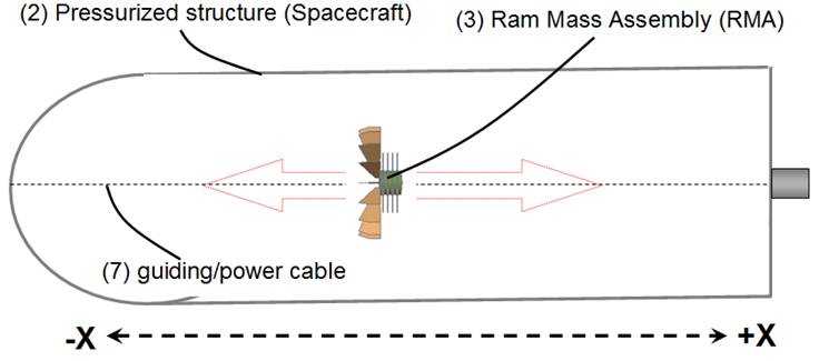
Fig 1
Fig 1 shows a
pressurized structure (2) or spacecraft in a micro-gravity environment, inside
the spacecraft is a 100k mass we call Ram Mass Assembly or RMA.
The RMA has
freedom to move across the length (not breadth) of the spacecraft.
For simplicity’s sake we will assume the
spacecraft also has a 100k mass. (RMA’s mass = Spacecraft’s mass)
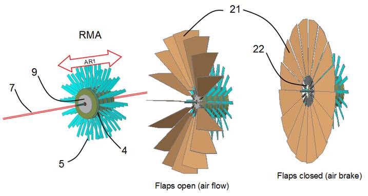
Fig 2 RMA
Illustrated (Fig
2) are the main elements of the RMA, electric motor 9, counter rotating rings 4
with rotors/propellers
Propulsion
Cycle
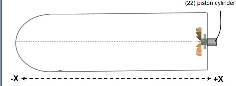
Fig 3
Illustrated in
Fig 3 is the RMA’s initial position (before starting propulsion cycle) at the
forward (+X) end of the pressurized structure, notice there is a piston
cylinder
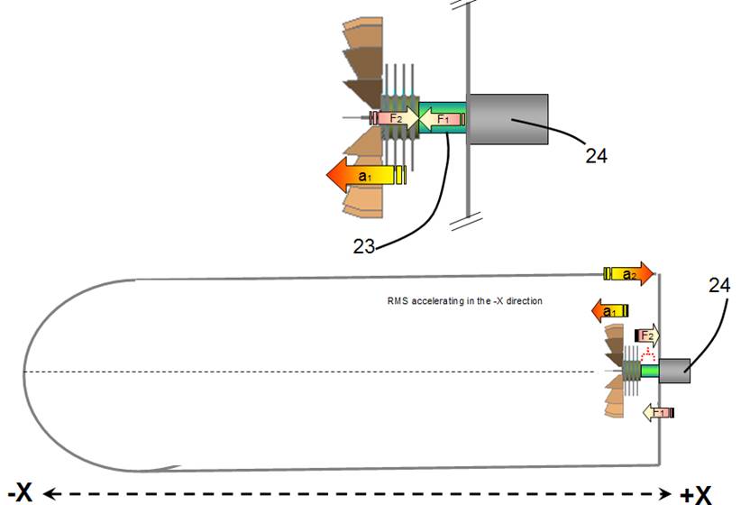
Fig 4
Cycle 1
The ramming
piston 23 is activated (with a 200n force) giving the RMA a push (F1) in the –X direction (Fig 4) accelerating it in the –X direction
(a1) with a velocity of 1 m/s, the opposite
force (F2) gives the pressurized structure an
acceleration in the +X direction (a2).
Therefore the RMA
will have a 1 m/s velocity in the –X direction (V1) and the spacecraft will
have a 1 m/s velocity in the +X direction (V2)
Fig 5
Cycle 2
The RMA advances in
the –X direction with a constant velocity V1 of 1m/s (RMA’s rotors 5 are off)
for a distance (D1) until it reaches a pre programmed position (P1).
(There is no
change in velocities V1 and V2 in this cycle)
Fig 6
Cycle 3
The instant The
RMA reaches position P1 (fig 6) its
rotor’s 5 are activated blowing air in the –X direction, this creates a force
(F3) that accelerate (a3) the RMA in the +X direction
The RMA (that was
traveling at constant velocity 1m/s in the –X direction) at first slows
(relative to the spacecraft’s velocity) until it reaches a relative velocity of
0 when it begins to gain speed in the +X direction till a pre-programmed
velocity (1m/s) is obtained then the
rotors stop.
During the time
interval the rotors/propellers are on, the flow of air molecules created exert
a force F4 against the spacecraft’s –X inner wall
accelerating (a4) its velocity in the –X direction, it also will at first slow to
0 then begin to gain velocity in the –X direction.
Fig 7
Cycle 4
At this cycle the
RMA is traveling (RMA’s rotors are off) with a 1 m/s velocity (V3) in the +X
direction and the spacecraft with a 1 m/s velocity (V4) in the –X direction.
Fig 8
Cycle 5
The RMA collides
with the spacecraft’s inner wall with force F5 giving it a +X acceleration (a5).
Resulting changes in acceleration on system
(spacecraft) in cycles 1 to 5
Cycle 1 produces
acceleration (a2) in the +X
direction.
Cycle 3 produces
acceleration (a4) in the -X
direction.
Cycle 5 produces
acceleration (a5) in the +X direction.
Cycles 2 and 4 do
not affect the spacecraft’s acceleration sufficiently to alter the final
result.
For simplicity,
we shall assume that in the presented
example no final change in acceleration affects the system (spacecraft),
this is possible if (a2) + (a5) = (a4)
We must not
forget that acceleration a4 is a product of
force F4, and force F4 can be increased or deceased by modifying the time interval the
RMA’s rotors are blowing air molecules against the spacecrafts inner –X wall
(can be also be modified by other factors.)
Now we will see
what effect the activation of the RMA’s air brake in cycle 2 has on force F4.
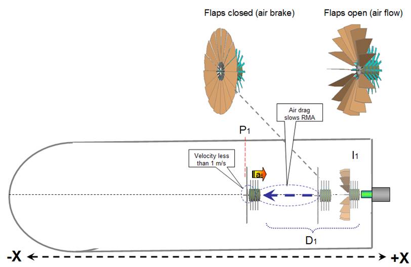
Fig 9
Cycle 2.1 (Modified, with air brake activated)
The instant the
RMA is pushed by the ramming piston 23 (cycle 1 fig 4) in the –X direction
obtaining a velocity of 1m/s, the flaps turn (almost) 90 degrees to closed
position offering maximum air drag
during its travel of distance D1, because of the increased drag, the RMA’s
relative velocity decreases as it
travels distance D1 and will be traveling at LESS than 1m/s.
when it reaches position P1.
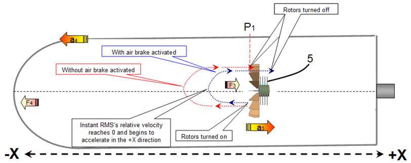
Fig 10
Cycle 3.1 (Modified)
The instant the
RMA reaches position P1, its flaps return
to their original position (open) and the RMA rotor’s are activated blowing air
in the –X direction, this creates a force (F3) that
accelerate (a3) the RMA in
the +X direction
As the RMA’s
relative velocity was decreasing
when it traveled distance D1, it arrives at point P1 with a velocity that is less than 1 m/s in the –X
direction therefore it needs a smaller time interval to reach a relative
velocity of 0, thus the rotors spend less time blowing air in the –X direction
consequently the force F4 against the spacecraft’s –X inner wall is
less and the spacecraft receives a lesser amount of acceleration in the –X
direction.
As we have
reduced the –X acceleration maintaining the +X acceleration unchanged the
spacecraft will accelerate with each cycle for as long a time as electricity is
transmitted to the RMA’s motor.
Experimental evidence
This page instructs how to
set up a test bed to observe the effect.
The described experiment is designed as an inexpensive DIY setup
so it can be duplicated with minimum time and expense.
Appendix A (Details of the cycles)
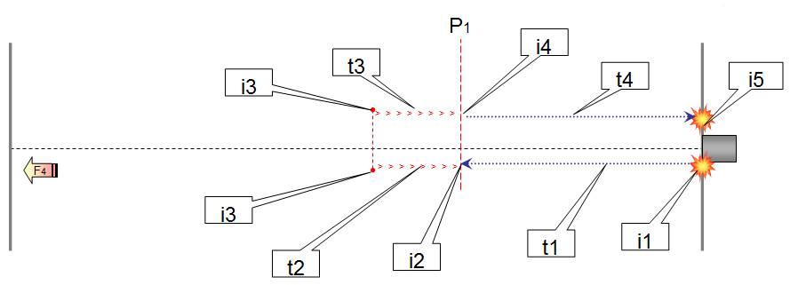
Fig 11
Detail of the cycles without activating
air brake (Fig 11)
|
|
|
Description |
Force on
spacecraft |
|
1 |
Instant 1 (i1) |
Ramming rod
gives the RMA a 100n push in the –X direction |
100n in the +X
direction (F2) |
|
2 |
Time interval 1
(t1) |
RMA travels at
a constant velocity of 1m/s in the –X direction |
0 |
|
3 |
Instant 2 (i2) |
RMA arrives at position
P1 with a 1m/s velocity, rotors are activated blowing air in the –X direction |
|
|
4 |
Time interval 2
(t2) |
The breeze
generated by the rotors collide with the spacecrafts –X inner hull incrementing
force F4 (in the –X direction) every second the rotors are blowing air in the
–X direction. The RMA’s slows
its relative –X velocity. |
Force F4 (in the –X direction) is incremented every second the rotors
are pushing air in the –X direction. |
|
5 |
Instant 3 (i3) |
The RMA’s
relative –X velocity reaches 0, and starts acceleration in the +X direction |
|
|
6 |
Time interval 3
(t3) |
The RMA’s
increases its relative +X velocity. |
Force F4 (in the –X direction) is incremented every second the rotors
are pushing air in the –X direction. Note: Force F4 is
directly proportional to the length of time intervals t2 and t3. |
|
7 |
Instant 4 (i4) |
RMA obtains a
relative +X velocity of 1m/s and rotors are deactivated. |
|
|
8 |
Time interval 4
(t4) |
RMA travels at
constant velocity of 1m/s in the +X direction |
0 |
|
9 |
Instant 5 (i5) |
RMA traveling
at 1m/s collides with the spacecrafts inner +X wall |
100n in the +X
direction (F5) (An electromagnet
is activated to attaching the RMA to the spacecraft’s wall to prevent a
“bounce effect”). |
|
We can conclude that if there is no
acceleration gain by the spacecraft it is because the breeze generated during
time intervals t2 and t3 is sufficient to create a force F4 that is exactly
equal to the opposite forces (F2 and F5). We can also
assume that in the described premise time intervals T1 and T4 are equal. |
|||
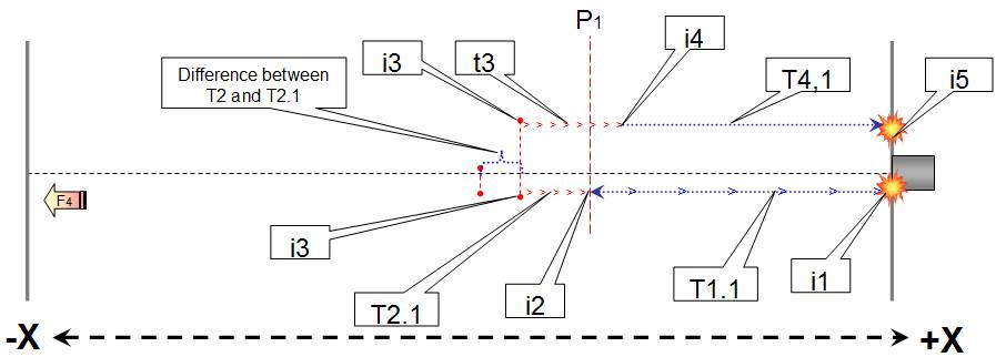
Fig 12
Detail of the cycles activating the air
brake (Fig 12)
|
|
|
Description |
Force on
spacecraft |
|
1 |
Instant 1 (i1) |
Ramming rod
gives the RMA a 100n push in the –X direction |
100n in the +X
direction (F2) |
|
2 |
Time interval
1.1 (t1.1) |
RMA’s air brake is
activated, the additional drag decreases the RMA’s –X velocity. The RMA takes
more time to arrive at position P1 but change in time interval T1.1 has no
effect on the spacecraft’s acceleration. |
0 |
|
3 |
Instant 2 (i2) |
RMA arrives at
position P1 with less than 1
m/s velocity, RMA’s air brake is deactivated, rotors are activated blowing air in the
–X direction |
|
|
4 |
Time interval
2.1 (t2.1) |
The RMA’s slows
its relative –X velocity. (Needs
less time to reach a relative velocity of 0 than time interval t2 because its
starting velocity is less than 1 m/s. Therefore t2
> t2.1) |
The breeze
generated by the rotors collide with the spacecrafts –X hull incrementing F4
(in the –X direction) every second the rotors are blowing air in the –X
direction |
|
5 |
Instant 3 (i3) |
The RMA’s
relative –X velocity reaches 0, and starts acceleration in the +X direction |
|
|
6 |
Time interval 3
(t3) |
The RMA’s
increases its relative +X velocity. |
Force F4.1 (in the –X direction) is incremented every second the rotors
are pushing air in the –X direction. Note: As t2 > t2.1
and forces F4 and F4.1 are directly proportional to the length of time
intervals air is blown in the –X direction we have: F4 = t2 + t3 And F4.1 = t2.1 + t3 As t2 > t2.1 then F4 > F4.1 As the forces
accelerating the spacecraft F2 and F5 are not affected by the use of the
RMA’s air brake we can assume a net +X force is exerted on the spacecraft
every cycle. Experiments where you can observe the
propulsion effect. |
|
7 |
Instant 4.
(i4.) |
RMA obtains a
relative +X velocity of 1m/s, rotors are deactivated. |
0 |
|
8 |
Time interval
4.1 (t4.1) |
RMA travels at constant
velocity of 1m/s in the +X direction |
0 |
|
9 |
Instant 5 (i5) |
RMA traveling
at 1m/s collides with the spacecrafts inner +X wall |
100n in the +X
direction (F5) (An
electromagnet is activated to attaching the RMA to the spacecraft’s wall to prevent
a “bounce effect”). |
|
We can conclude
that as the –X force F4.1 is less than –X force F4 but +X forces F2 and F5
remain unchanged, the end result is a net +X force on the spacecraft. |
|||