Construction of a Simple Dynamic Tests Rig (doc v01)
Invitation to Invest / Contribute
Introduction
This introduction is for persons that are NOT familiar with the Fluid Space Drive (FSD) concept, if you have knowledge of the FSD please jump directly to Dynamic Test Rig
The Fluid Space Drive (FSD) is a simple practical method of propelling spacecraft in micro gravity environment without expelling mass/propellant therefore permitting fast exploration of our solar system and beyond (See video description)
The FSD works because of two physical phenomena that are easy to observer:
One:
The force exerted by a moving object against a target surface on collision depends on the object’s mass and velocity (at the moment of impact) regardless of what method was used to accelerate the mass (slingshot, cannon, air, electric or whatever), and the force will be the same regardless of the distance traveled from the source that expelled the mass (assuming the velocity at the instant of collision is unchanged).
Example
If a mass (100 kilos) collides against a surface with a relative velocity of 1m/s ( meters/second) it will exert a force (100n) against the surface, and the force will be the same no matter what method was used to accelerate the mass, and regardless of the distance traveled from the source that expelled the mass.
The 100 kilo mass may travel
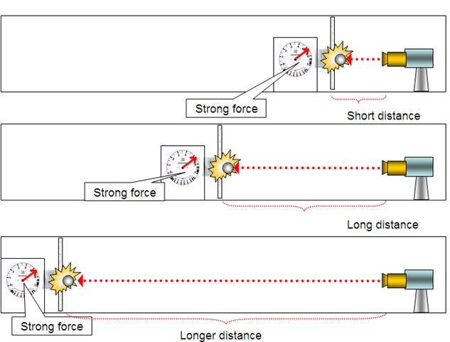
Fig 1
Two:
If we blow air against a target surface, the resulting force is inversely proportional to the distance between the target surface and the source of the breeze (figs 2a and 2b), more on empirical observations can be seen here.
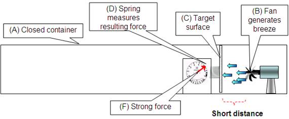
Fig 2a
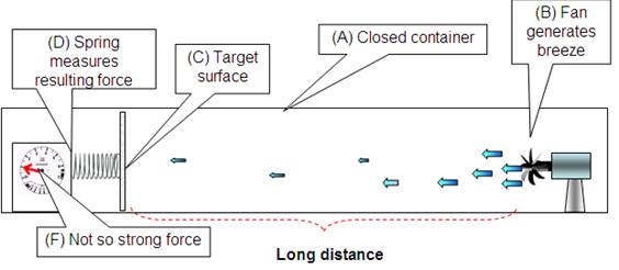
Fig 2b
Note:
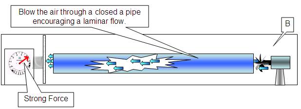
Fig 2c
Remember the closed container (A) must be large enough so that turbulent flow is generated, if we blow the air through a closed channel such as a pipe (Fig 2c), a laminar or streamline flow will be encouraged, the force against a target surface will not necessarily be dependant on the distance.
In the laminar flow example we can use the Navier–Stokes equations for calculations, with turbulent flow calculations are more complex.
Therefore if we put two pressurized spaceships of the same mass (spaceship A will need ballast) in orbit (fig 3), both with a free floating motor propeller assembly inside the spacecraft.
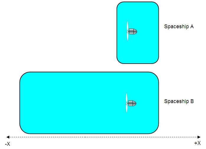
Fig 3
If we turn on the propellers in spaceships A and B so that they blow a breeze in the –X direction, both propeller assembles will accelerate in the +X direction (Fig 4), let us say that each free propeller assembles suffers a ∆1 mps velocity change (fig 4).
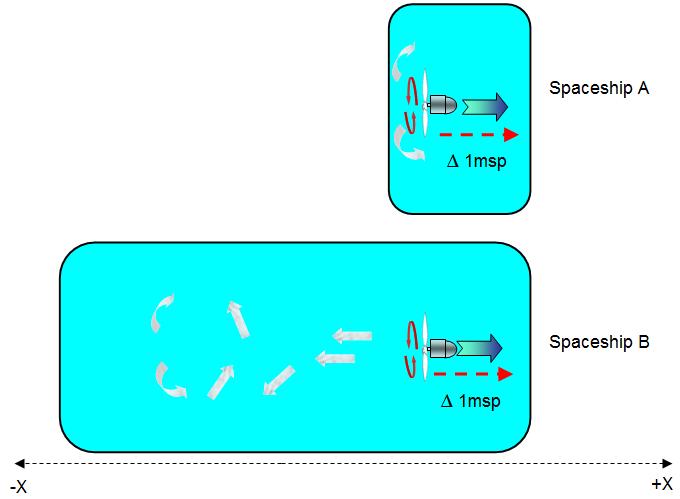
Fig 4
When the propeller assembles collide with the spacecrafts internal +X hull (Fig 5a), as they are traveling with a velocity (relative to the spaceship) of 1m/s with a 100k mass, they will exert a 100 newton force in the +X direction.
This is true for both spacecrafts as the mass and relative velocity of both propeller assembles is the same.
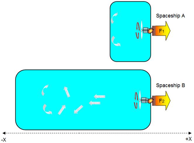
Fig 5a
Propeller assembles A (100k mass) x velocity (1m/s) = 100 newtons = F1.
Propeller assembles B (100k mass) x velocity (1m/s) = 100 newtons = F2
F1 = F2 = 100 newtons.
Will the spaceships gain any forward velocity? We have only taken into consideration the force against the spacecrafts internal +X hull, there is also the force excreted by the air molecules collisions against the spacecraft’s internal –X hull that tend to create a balancing counterforce in the –X Direction (Fig 5b).
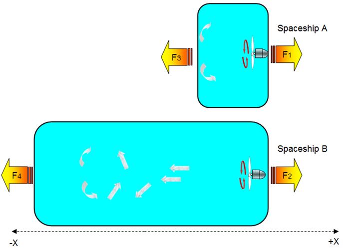
Fig 5b
But will the forces F3 and F4 also be equal, this is where common sense appears to conflict with scientific principal.
To a untrained observer, common sense would dictate that F3 will be greater than F4 because the inner hull receiving the air currents are very close to the propellers generating the breeze, while the –X hull in spacecraft B is a longer distance from the source to the breeze and may deduce that the greater the distance that separates a surface from a source of breeze, the less the resulting force will affect the surface.
Seems logical at
first glance.
But the trained scientist will patently indicate that the law of conservation of linear momentum, a fundamental law of nature clearly states that if no external force acts on a closed system of objects, the momentum of the closed system remains constant.
In other words whatever combinations of actions the masses contained in the spaceship execute, be they the propeller assembles or the billions and billions of tiny gas (air) molecules, if no matter is allowed to leave the closed system (spaceship), the system will not accelerate.
As it does not accelerate (it may oscillate but not accelerate) it means that the forces in the +X direction (the propeller assembly’s collision with the +X hulls) are balanced by equal forces in the –X direction, therefore forces F1 = F2 = F3 = F4.
If the untrained observer insists with his deduction that while F1 is obviously equal to F2, to him it is just as obvious that force F3 cannot be equal to F4, and insists that at least spaceship B must gain velocity.
As the scientist and the untrained observer can not agree, the scientist decides to create an experiment, for in science differences are finally settled with experimentation and observations, not thought experiments however entertaining.
Even though a true 0 gravity test is the best and final way
to prove a “propellantless” engine works, it is possible to demonstrate the
feasibility and efficiency of the
Description
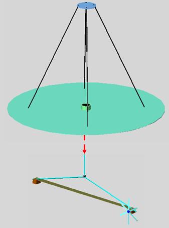
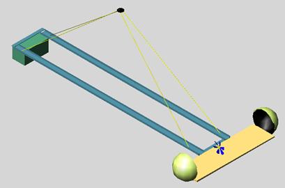
Fig 6 shows a motor and propeller (or wheel) balanced by a counter weight hanging from a string, this permits the assembly to easily rotate around the vertical axis.
|
Fig 6 Balancing motor assembly |
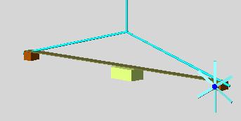
Fig 7 illustrates that the motor assembly can have a wheel attached (fig 7a) or a propeller (Fig 7b)
|
Fig 7a Fig 7b |
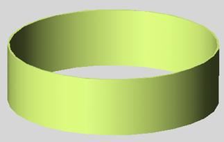
The balancing motor assembly is inside a perimeter cylinder structure (Fig 9d), balancing motor assembly and perimeter cylinder structure may rotate independently (until the balancing motor assembly bumps into the separator borders (fig 8 and fig 9b),
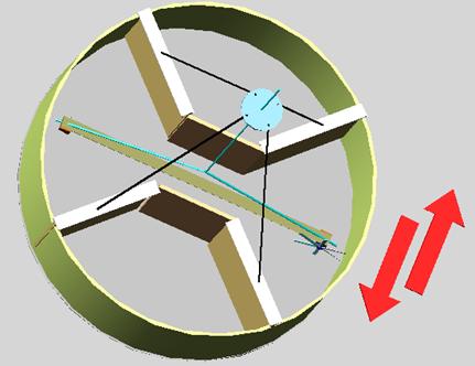
Fig 8
|
Fig 7 illustrates
the assembly
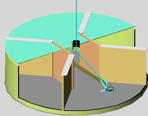
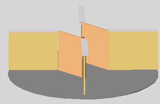
As illustrated in figs 9 and 10 (cutaway) the balancing motor can turn on its vertical axis independently of the surrounding perimeter / support / separators for approximately 40º angel before colliding with one of the separators. (b)
b
b Fig 10 |
a
d
e b b Fig 9 |

|
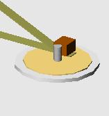
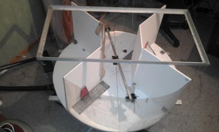
Photograph shows a partially assembled test apparatus, the balancing motor assembly c can be seen as can the separator panels on the circular bottom. (The test assembly as the balancing motor assembly are hanging on strong threads that are not visible in this photograph) |
Fig 12 |
Testing
1) Using a
wheel in direct contact with the perimeter surface.
2) Turning on the
motor/propeller near (almost touching) “rear” separator
3) Turning on the motor/propeller as far from the “rear” separator as possible.
Using a wheel in direct contact with the perimeter
surface
If we attach the wheeled assembly to the motor (fig 7a) in such a manner that the wheel is in contact with the perimeter circle so that when the motor is turned on the wheel will “roll” on the cylinder (Fig 13)
θ 2 θ 1
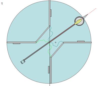
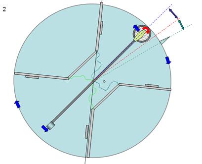
Fig 13a Fig 13b
Fig 11b illustrates what happens when we turn on the motor so that the wheel turns in a clockwise direction, the motor / wheel assembly pushing against the perimeter cylinder will move in a counter clockwise direction (θ 1) while the perimeter cylinder will turn in a clockwise direction (θ 2).
The ratio between the counter clockwise angular displacement of the balancing motor assembly (θ 1) and the clockwise angular displacement of the perimeter cylinder (θ 2) will depend on the ratio between the masses of the objects, if they have equal mass (this can be controlled by adding mass where necessary) the angular displacements will be equal. (Fig 13b)
If we reverse the direction of the motor the objects will return to their original position. It is not possible to give the perimeter cylinder a constant angular acceleration if the balanced motor assembly is restrained to a fixed angle by separating panels.
At most we can obtain a cyclical clockwise anticlockwise oscillation
Turning on the motor/propeller near (almost touching)
“rear” separator
If we replace the wheeled assembly with the propeller (Fig 7b) and position the motor/propeller assembly as close as possible to the “rear” separator (fig 14a), turning on the motor blows air directly against the “rear” separator that giving the perimeter cylinder a clockwise movement, the balancing motor/propeller assembly will accelerate in the counter clockwise direction (fig 14b) until it collides with the “forward” separator bringing the perimeter cylinder’s clockwise spin to a standstill.
In the described configuration it is difficult to obtain an increment in rotation of the perimeter cylinder, just as spacecraft A (fig 5) will not accelerate.
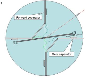
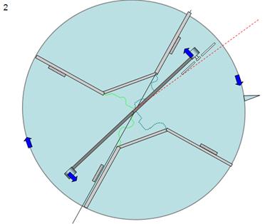
Fig 14a Fig 14b
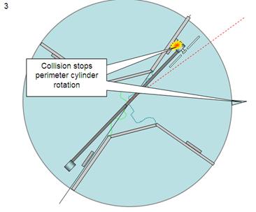
Fig 14c
Video 1
Turning on the motor/propeller as far from the “rear” separator
as is possible
If we position the balancing motor assembly’s initial
position far form the “rear” separator (fig 15a), with a approximate 35º angle
(θ 1), when we
turn on the propeller the balancing motor assembly accelerates in the counter
clockwise direction (fig 15b) as in the previous experiment, but the perimeter
cylinder’s clockwise acceleration is significantly less than the previous
experiment, this is because the force exerted against an object by a (non
laminar) gas flow is inversely proportional to the distance separation gas
source from the target surface (separator) (see)
The instant of collision between the balancing motor assembly and the “forward” separator (fig 15c) finds the perimeter cylinder has made only a small clockwise movement, and the momentum transferred by the balancing motor assembly to the perimeter cylinder is sufficient to accelerate it in the counter clockwise direction beyond its original position and continue turning in the counter clockwise direction (fig 15d).
By repeatedly inverting the direction of the propeller (Note 1) it is possible to continually “bump” the “forward” separator constantly increasing the perimeter cylinders counterclockwise velocity just as spacecraft B (fig 5) accelerates with every collision.
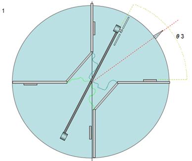
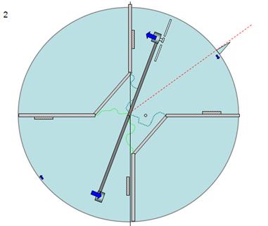
Fig 15a Fig 15b
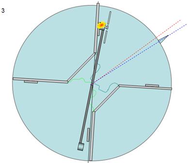
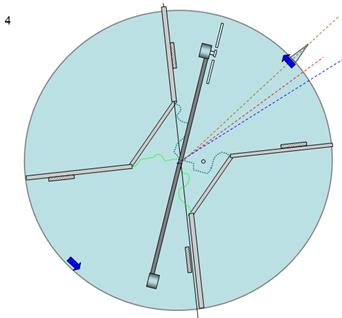
Fig 15c Fig 15d
Video 2
Video 3
What is observed
when we turn on the motor, the clockwise angular displacement of the perimeter cylinder is depended on the distance that separate the propeller from the “rear” separator, (Videos 1, 2 and 3), this is because the force exerted against an object by a (non laminar) gas flow is inversely proportional to the distance separation gas source from the target surface (separator) (see)
The balanced motor assembly continues to gain angular velocity until it collides with one of the separators (Fig 15c), it transfers momentum to the perimeter cylinder that gains velocity in the counter clock wise direction, the balanced motor assembly bounces in the clockwise direction, the cycle can be repeated indefinitely by changing the direction of the propeller (see Note 1) at the appropriate moment (see videos 2 and 3)
Test Rig 2 (under construction as you read)
Video 4
The video shows a test rig 2 setup, this configuration was a disappointment (not stable) but is sufficient to illustrate the mechanism, a video of stable test bed of this configuration will be on this site shortly
Invitation to Invest / Contribute
To control the propeller motor (on-off-left spin-right spin) it is best to use a RC controller so that no external cables protrude from the assembly.
Suggested method:
Obtain an inexpensive toy RC car or other toy
Remove the RC circuit (generally includes the battery compartment) (fig 11)
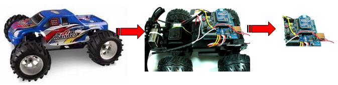
Fig 16
Connect the control wires of one of the toys motors (most have two or more) to the propeller motor, in this example a normal LEGO motor (fig 12)
This setup will control the propellers direction remotely.
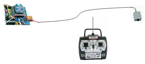
Fig 18